Brief summary: Sunday Optics, an optical Spherical Lens manufacturer, explains that a plano-concave lens is normally installed with its concave surface facing the incoming collimated beam when the goal is to produce a clean, controlled diverging beam. This orientation often reduces spherical aberration compared with placing the plane surface first, but it is not a universal rule. The correct direction depends on beam convergence, lens spacing, aperture, wavelength, coating, working distance, and the optical system’s final performance target. A quick ray-trace or optical-design check should confirm the choice before production.
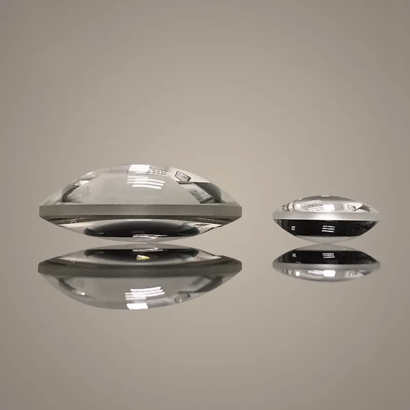
In a typical optical system, place a plano-concave lens with the concave curved surface toward the incoming collimated or nearly collimated beam and the plane surface toward the diverging output.
This arrangement is commonly preferred because it can reduce spherical aberration and produce a more predictable diverging wavefront. However, the best orientation is determined by the complete optical design rather than by lens shape alone.
Which Way Should a Plano-Concave Lens Face?
Practical orientation rule
- Collimated beam entering a negative lens: usually place the concave surface toward the incoming beam.
- Beam already converging or diverging: evaluate both orientations with optical-design software or a controlled bench test.
- Strongly converging or high-numerical-aperture systems: do not rely on the basic rule alone; surface orientation can materially affect aberration and focus.
- Laser systems: check damage threshold, coating performance, ghost reflections, and the position of the virtual focus.
- Precision imaging systems: use a ray trace to compare wavefront error, spot size, distortion, and field performance.
Search Intent and Content Perspectives Found Across the Leading Independent Resources
The search results for this subject are generally dominated by technical education pages, lens-manufacturer application notes, optical-design references, and engineering explainers rather than conventional news articles. The following ten independent resource types represent the main perspectives users typically encounter on the front page for queries about plano-concave lens orientation. Exact rankings can change by country, device, date, and personalization.
- Edmund Optics technical resources
- Primary intent: learn the correct orientation for plano-convex and plano-concave lenses.
- Perspective: practical lens-handling guidance supported by aberration concepts, diagrams, and application examples.
- Newport technical articles and lens-selection guides
- Primary intent: select and position optical components for laser and imaging systems.
- Perspective: engineering-focused discussion of focal length, lens geometry, wavelength, coatings, and performance trade-offs.
- Thorlabs educational and catalog documentation
- Primary intent: understand the specifications and use of negative lenses in laboratory setups.
- Perspective: product-centered guidance emphasizing focal length, clear aperture, substrate, AR coating, and mounting.
- RP Photonics Encyclopedia
- Primary intent: understand the physics of diverging lenses and aberrations.
- Perspective: theory-based explanations of refractive power, wavefronts, Gaussian beams, and optical aberrations.
- Opto Engineering educational articles
- Primary intent: apply lens principles to machine vision and imaging.
- Perspective: system-level treatment of field of view, distortion, image quality, and lens placement.
- Wikipedia and university optics references
- Primary intent: obtain a foundational definition of plano-concave lenses.
- Perspective: introductory explanations of negative focal length, refraction, and virtual images.
- Laser physics and photonics tutorial websites
- Primary intent: understand how a negative lens expands or diverges a laser beam.
- Perspective: practical beam-expander design, Gaussian-beam propagation, and spacing calculations.
- Optical component manufacturers and catalog notes
- Primary intent: compare lens materials, coatings, tolerances, and available focal lengths.
- Perspective: specification-driven advice with emphasis on manufacturability and application suitability.
- Engineering forums and professional Q&A discussions
- Primary intent: solve a practical mounting or alignment problem.
- Perspective: experience-based recommendations, often including warnings about orientation, surface contamination, and alignment.
- Optical-design software documentation
- Primary intent: verify the effect of lens orientation through numerical modeling.
- Perspective: quantitative comparison of spot diagrams, wavefront error, ray fans, and tolerance sensitivity.
Six SEO-Friendly Article Outline Options
Outline 1: Direct Answer and Installation Guide
- Define a plano-concave lens and its negative focal length.
- Answer which side should face the incoming beam.
- Explain why the concave surface commonly faces collimated light.
- Show correct and incorrect installation diagrams.
- List exceptions requiring ray tracing.
- Provide a final installation checklist.
Outline 2: Plano-Concave Lens Orientation for Laser Beam Expansion
- Explain how a plano-concave lens increases beam divergence.
- Differentiate collimated, converging, and diverging input beams.
- Discuss virtual focal points and lens spacing.
- Explain coating, damage-threshold, and ghost-reflection considerations.
- Provide a beam-expander alignment procedure.
Outline 3: Aberration-Based Comparison of Both Orientations
- Introduce spherical aberration and marginal rays.
- Compare curved-side-first and plane-side-first mounting.
- Explain the effect of aperture and numerical aperture.
- Describe when orientation has little practical impact.
- Recommend software verification for precision applications.
Outline 4: How to Choose the Correct Plano-Concave Lens
- Calculate required focal length from the target divergence.
- Select glass type and refractive index.
- Choose diameter, clear aperture, and center thickness.
- Specify wavelength and antireflection coating.
- Check surface quality, power tolerance, and centration.
Outline 5: Common Installation Mistakes
- Installing the lens backward without checking the optical design.
- Confusing a plano-concave lens with a plano-convex lens.
- Using an unsuitable coating for the operating wavelength.
- Clamping the optic too tightly.
- Ignoring beam clipping and clear-aperture limits.
- Failing to verify the output beam after installation.
Outline 6: Plano-Concave Lens Orientation for Imaging Systems
- Explain the role of a negative lens in correcting optical power.
- Discuss object distance, image distance, and virtual images.
- Compare orientation effects at low and high numerical aperture.
- Evaluate field curvature, distortion, and spherical aberration.
- Explain how to validate the design with a spot diagram and tolerance analysis.
Outline 7: Manufacturer and Procurement Guide
- Identify the required optical and mechanical specifications.
- Compare standard catalog lenses with custom optics.
- Ask the manufacturer for coating and damage-threshold data.
- Confirm drawings, inspection reports, and tolerances.
- Inspect and orient the received lens before assembly.
What Is a Plano-Concave Lens?
A plano-concave lens has one flat surface and one inward-curved surface. It is normally a negative lens, meaning that it causes parallel incident rays to spread apart after transmission.
- Plano: one optical surface is flat.
- Concave: the opposite surface curves inward relative to the incident medium.
- Negative focal length: transmitted rays appear to originate from a virtual focal point on the input side.
- Typical uses: beam expansion, divergence control, focal-power balancing, relay systems, and aberration correction.
For a thin lens in air, the approximate focal length can be related to the surface curvature and refractive index using the lensmaker relationship:
1/f ≈ (n − 1)(1/R1 − 1/R2)
For a plano-concave lens, one surface has effectively infinite radius, while the curved surface provides most of the lens power. In real systems, thickness, wavelength, material dispersion, and surface shape must also be included.
Why the Concave Surface Usually Faces the Incoming Collimated Beam
When parallel rays enter a plano-concave lens, the concave-first orientation generally provides a smoother distribution of refraction through the lens. It is commonly selected to reduce spherical-aberration effects and to make the output divergence more consistent across the usable aperture.
- Improved marginal-ray behavior: rays near the edge of the aperture can deviate differently from paraxial rays because of surface curvature. Orientation can reduce this difference.
- More predictable divergence: the emerging beam is easier to align with a downstream aperture, detector, or second lens.
- Better image quality: in many low- to moderate-aperture applications, the preferred orientation reduces blur caused by spherical aberration.
- Reduced sensitivity in practical setups: the correct orientation can make performance less dependent on using only the central portion of the lens.
The improvement is not unlimited. A plano-concave lens is a simple singlet, so it may still produce spherical aberration, chromatic effects, coma, and other errors. If performance requirements are demanding, a multi-element design or an aspheric optic may be more appropriate.
Step-by-Step Method for Installing a Plano-Concave Lens
Step 1: Identify the input beam condition
- Measure or calculate whether the beam is collimated, converging, or diverging before it reaches the lens.
- Record the beam diameter at the lens location.
- Determine whether the beam is Gaussian, multimode, broadband, or spatially filtered.
- Check the angle of incidence and polarization if the system uses a laser.
Step 2: Identify the lens surfaces
- The flat face has a visibly planar profile and usually reflects a straightforward image.
- The concave face curves inward and may be easier to identify by edge thickness and reflected-light geometry.
- Use the manufacturer’s drawing or engraving rather than guessing from appearance.
- Do not touch either optical surface with bare fingers.
Step 3: Start with the standard orientation
For a collimated beam that must be made divergent, install the lens with the concave side toward the incoming beam. The plane side normally faces the expanding output beam and the next optical component.
Step 4: Center the lens mechanically
- Use a suitable lens mount with the correct diameter range.
- Keep the optic centered on the mechanical and optical axes.
- Avoid excessive retaining-ring pressure, which can introduce stress and distortion.
- Ensure that the beam does not clip the clear aperture.
Step 5: Align the optical axis
- Use an alignment laser, irises, or an autocollimator where appropriate.
- Adjust tip and tilt until the transmitted beam follows the intended axis.
- Inspect the beam at more than one downstream distance to identify angular misalignment.
- For a Gaussian beam, compare the measured beam radius with the predicted propagation.
Step 6: Verify performance
- Measure output beam diameter at two or more distances.
- Check the beam profile for asymmetry, clipping, rings, or hot spots.
- Compare the measured divergence with the design value.
- Reverse the lens only as a controlled test if orientation is uncertain.
- Use a wavefront sensor, camera, knife-edge measurement, or beam profiler for precision work.
When the Plane Surface May Face the Incoming Beam
The concave-first arrangement is a practical default, not an absolute law. The plane surface may face the source when the complete optical design benefits from that configuration.
- Pre-existing beam convergence: a lens positioned inside a converging beam may have a different optimum orientation than one receiving collimated light.
- Custom aberration balancing: a designer may deliberately reverse the lens to balance aberrations from another element.
- Mechanical packaging: the mount, barrel, retainer, or adjacent component may require a particular surface direction.
- Coating or contamination concerns: one surface may have a coating or protective treatment better suited to the source environment.
- Very low numerical aperture: orientation may have negligible measurable impact when the beam uses only the paraxial region.
- Multi-element assemblies: the best direction must be determined by the full prescription rather than by an isolated-lens rule.
How to Choose Between the Two Orientations with Optical Design Software
Build two identical models
- Create one model with the concave surface facing the source.
- Create a second model with the plane surface facing the source.
- Use the same lens thickness, material, wavelength, aperture, object distance, and image distance.
Compare measurable performance criteria
- RMS and peak-to-valley wavefront error.
- Transverse ray aberration and longitudinal spherical aberration.
- RMS spot radius and encircled energy.
- Beam divergence and virtual-focus location.
- Throughput and clear-aperture utilization.
- Sensitivity to decenter, tilt, spacing, and manufacturing tolerances.
Software such as Zemax OpticStudio, CODE V, Oslo, or an equivalent ray-tracing package can provide a quantitative answer. For a simple low-power system, a laboratory comparison may be sufficient; for imaging, metrology, lithography, or high-power laser work, numerical verification is strongly recommended.
Plano-Concave Lens Orientation in Laser Beam Expansion
A plano-concave lens can be paired with a positive lens to create a Galilean beam expander. The negative lens is typically placed before the positive lens so that the beam diverges first and is then recollimated by the positive element.
- Approximate magnification: for a Galilean expander, the beam-expansion ratio is approximately the magnitude of the positive focal length divided by the magnitude of the negative focal length.
- Lens spacing: the separation is approximately the difference between the positive and negative focal-length magnitudes for an afocal arrangement.
- Beam clearance: confirm that the expanding beam remains inside the second lens’s clear aperture.
- Adjustment: use a translation stage to optimize collimation after mechanical alignment.
- Laser safety: verify coating wavelength, pulse duration, average power, peak power, and manufacturer-stated laser-damage threshold.
For a Gaussian beam, the simple geometric focal-length calculation is only an approximation. The complex beam parameter, waist location, Rayleigh range, and lens separation should be included in a more accurate design.
How Lens Orientation Affects Spherical Aberration
Spherical aberration occurs because rays passing through different radial zones of a spherical surface do not refract to exactly the same apparent focus. The effect becomes more important as the beam diameter, numerical aperture, or marginal-ray angle increases.
- Small beam near the optical axis: the difference between orientations may be minor.
- Large beam diameter: edge rays experience stronger aberration, making orientation more important.
- Short focal length: stronger lens power usually increases sensitivity to surface orientation.
- High-index glass: refractive power and aberration behavior change with material index.
- Broad wavelength range: chromatic focal shifts may become more important than orientation alone.
Important Specifications to Confirm Before Ordering
- Negative effective focal length: select the focal length according to the desired divergence or optical-power correction.
- Diameter and clear aperture: make sure the usable aperture exceeds the beam diameter with an appropriate margin.
- Substrate: choose fused silica, BK7, or another glass according to wavelength, thermal load, and environmental requirements.
- Antireflection coating: specify the operating wavelength or wavelength band.
- Surface quality: confirm scratch-dig and cosmetic requirements.
- Surface accuracy: verify power, irregularity, and transmitted-wavefront requirements.
- Centration: check wedge and optical-axis alignment for sensitive systems.
- Edge thickness: ensure that the lens can be safely mounted without interference.
- Laser-damage threshold: request data appropriate to continuous-wave, nanosecond, picosecond, or femtosecond operation.
- Environmental durability: consider humidity, temperature cycling, vacuum, cleaning chemicals, and abrasion.
Common Plano-Concave Lens Installation Mistakes
Installing the lens by shape alone
A lens can appear correctly oriented while being reversed relative to the optical prescription. Always confirm the direction from the drawing, optical-design file, or assembly instruction.
Assuming every system uses collimated light
The standard concave-first rule is most useful for a collimated or nearly collimated input beam. A beam with significant convergence or divergence may require a different optimization.
Ignoring the clear aperture
Even if the nominal lens diameter is large enough, the usable clear aperture may be smaller because of bevels, mounts, retaining rings, or coating masks.
Overtightening the mount
Mechanical stress can distort the lens and degrade the transmitted wavefront. Tighten retaining components only enough to secure the optic.
Using the wrong coating
A coating designed for visible wavelengths may perform poorly at ultraviolet or infrared wavelengths. Confirm coating range and angle-of-incidence limits.
Cleaning incorrectly
- Use clean, oil-free air or nitrogen to remove loose particles.
- Follow the manufacturer’s recommended solvent and tissue procedure.
- Do not wipe a contaminated surface aggressively.
- Wear powder-free gloves and handle the lens by its edge.
Frequently Asked Questions
Should the concave side of a plano-concave lens face the laser?
Usually, yes, when the laser beam is collimated and the lens is being used to create controlled divergence. Confirm the final result with a beam measurement or ray trace, especially for high-power or high-aperture systems.
What happens if a plano-concave lens is installed backward?
The lens will still have negative optical power, so it may still diverge the beam. However, spherical aberration, beam quality, virtual-focus position, and system performance may change.
Does lens orientation change the focal length?
For an ideal thin lens, reversing the lens does not change its paraxial focal length. In a real thick lens, orientation can change aberrations, principal-plane locations, and effective system behavior.
Can a plano-concave lens collimate a beam?
A single plano-concave lens normally makes a collimated beam diverge. It can help collimate a diverging beam only when the source position, lens power, and system geometry are correctly selected, and it is often paired with a positive lens.
Is a plano-concave lens better than a negative meniscus lens?
Not automatically. A negative meniscus lens may provide better aberration control in some systems, while a plano-concave lens may be simpler, thinner, less expensive, or easier to source. Compare the complete optical prescription.
Key Design Points That Are Often Overlooked
Account for the lens thickness and principal planes
The thin-lens approximation is useful for an initial estimate, but thick-lens effects matter when the lens is strong, the spacing is short, or the system requires precise focus and divergence control.
Include wavelength-dependent refractive index
Focal length varies with refractive index, and refractive index varies with wavelength. A lens optimized at 632.8 nm may not perform identically at 405 nm, 532 nm, 1,064 nm, or broadband wavelengths.
Check thermal and laser-damage effects
Absorption, coating heating, contamination, and thermal lensing can alter performance even when the geometric orientation is correct. High-power applications require manufacturer data and appropriate safety margins.
Consider ghost reflections and back-reflection
Flat surfaces can create noticeable return reflections, particularly in laser systems and detectors. A slight intentional tilt, suitable AR coating, or wedged optic may be necessary when feedback is unacceptable.
Evaluate polarization and angle of incidence
Coating transmission and reflection vary with polarization and incidence angle. Avoid assuming that normal-incidence catalog data applies to a tilted, polarized beam.
Do not confuse beam divergence with poor alignment
A correctly oriented plano-concave lens intentionally increases divergence. If the output beam is asymmetric or the beam axis walks laterally, investigate decenter, tilt, surface defects, mount stress, and clipping rather than changing orientation immediately.
Final Implementation Checklist
- Confirm that the component is actually a plano-concave negative lens.
- Determine whether the incoming beam is collimated, converging, or diverging.
- For a collimated input, begin with the concave surface facing the source.
- Verify focal length, diameter, clear aperture, substrate, and coating.
- Check the beam diameter against the clear aperture at every relevant position.
- Mount the optic without excessive mechanical stress.
- Align the lens to the optical axis using irises, targets, or an autocollimator.
- Measure divergence and beam profile after installation.
- Compare both orientations by ray tracing when image quality or beam quality is critical.
- Request coating, surface-quality, centration, and laser-damage data from the optical manufacturer.
- Document the final orientation in the assembly drawing and maintenance instructions.
Conclusion
The practical answer is straightforward: for a plano-concave lens receiving a collimated beam, install the concave side toward the incoming beam in most optical systems. This orientation commonly provides better control of spherical aberration and beam divergence than the reversed arrangement. Nevertheless, the correct engineering decision depends on the complete optical prescription, including beam condition, aperture, wavelength, lens material, coating, spacing, and performance requirements. Use the standard orientation as the starting point, then validate it with ray tracing or measurement before finalizing the assembly.


