Sep. 17, 2026
Share:
Choosing the correct plano-convex lens for laser collimation does not need to be complicated. At Sunday Optics, we recommend a practical process: define the laser wavelength and beam diameter, calculate the required focal length, select the substrate and AR coating, confirm the damage threshold, and verify optical quality before installation. By following these steps, engineers can achieve a more stable collimated beam, reduce divergence, and avoid costly trial-and-error replacements.
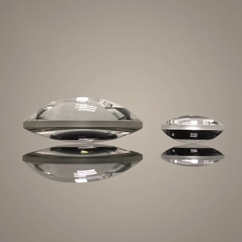
A plano-convex lens has one flat surface and one convex spherical surface. It is a positive focal-length lens designed to converge light or collimate a diverging beam when the light source is positioned close to its front focal plane.
For many laser systems, a plano-convex lens offers an effective balance of:
However, selecting a lens only by diameter or focal length can produce poor results. Collimation quality also depends on the Spherical Lens geometry, wavelength, beam waist, source position, lens orientation, surface quality, and coating performance.
As an experienced optical spherical lens manufacturer, Sunday Optics helps customers match these specifications to real applications such as laser marking, fiber coupling, barcode scanning, LiDAR, interferometry, medical instruments, and industrial alignment systems.
Before choosing a plano-convex lens, I first collect the laser parameters. These values determine whether the lens will provide sufficient beam expansion, acceptable wavefront quality, and safe power handling.
Record the following information:
The wavelength is especially important because the refractive index of the optical material changes with wavelength. This affects the effective focal length and spherical aberration.
For example, a lens designed for 1064 nm with a suitable AR coating may perform poorly at 532 nm if the coating transmission is not optimized for green laser light. A visible-light coating should not automatically be used for near-infrared systems.
For a small, approximately collimated laser beam, the approximate output beam diameter after a plano-convex lens can be estimated as:
[ D \approx 2f\theta ]
Where:
If the input beam is already close to collimated, the lens may be used with a pinhole, fiber end face, diode emitter, or beam waist located near the focal plane.
For fiber-coupled lasers, the required focal length is often related to the fiber mode-field diameter and numerical aperture. For laser diodes, the fast-axis and slow-axis divergence should be treated separately because the beam is usually elliptical and astigmatic.
A common mistake is selecting a focal length based only on the physical distance available. I recommend calculating the optical requirement first, then checking whether the mechanical envelope can accommodate the lens and mount.
The lens clear aperture must be larger than the beam diameter. For practical alignment tolerance, I generally recommend leaving at least 10% to 20% additional clear aperture beyond the maximum beam diameter.
For example:
This margin helps prevent beam clipping caused by decentering, vibration, thermal drift, or mounting tolerances.
The lens diameter should also account for:
If the beam passes through the edge of the lens, the result may include diffraction, aperture clipping, reduced power transmission, and unstable far-field performance.
The substrate must match the wavelength, power density, environmental conditions, and required transmission band.
Common materials include:
| Substrate | Typical advantages | Common applications |
|---|---|---|
| N-BK7 | Good visible and near-IR transmission, economical | General laboratory and industrial optics |
| Fused silica | Low absorption, high thermal stability, UV transmission | High-power lasers, UV systems, precision instruments |
| UV fused silica | Excellent UV performance and low fluorescence | UV laser collimation and photolithography |
| Calcium fluoride | Broad spectral transmission and low dispersion | Specialized UV and IR systems |
| Sapphire | High hardness and durability | Harsh environments and protective optical assemblies |
For low- to moderate-power visible lasers, N-BK7 is often a practical option. For high-power 1064 nm systems or UV lasers, fused silica may offer better thermal and transmission performance.
Substrate selection should not be based only on material price. Thermal lensing, absorption, coefficient of thermal expansion, and laser-induced damage must also be evaluated.
An uncoated glass surface reflects approximately 4% of incident light per surface under normal conditions. A plano-convex lens has two surfaces, so this loss can become significant in a precision laser system.
A wavelength-specific AR coating can improve transmission and reduce:
When ordering from Sunday Optics, specify:
Typical coating choices may include:
The coating must also be compatible with the laser damage threshold. A coating optimized for low-power imaging may not be appropriate for a high-energy pulsed laser.
The focal length determines the distance between the lens and the point source or beam waist. For collimating a diverging beam, position the laser emitter or fiber end near the plano-convex lens front focal point.
For most collimation applications, the curved surface should face the incoming diverging beam and the plane surface should face the collimated output. This orientation generally reduces spherical aberration compared with placing the flat surface toward the divergent source.
The exact best orientation can depend on:
The lens should be mounted so that the source-to-lens distance can be adjusted finely. A threaded translation tube or precision XYZ stage is often more useful than a fixed mount because the true focal position may differ slightly from the nominal catalog value.
Do not confuse effective focal length with back focal length.
The difference matters when designing a compact collimation assembly. Sunday Optics can provide the relevant mechanical and optical drawings so that the lens seat, spacer, and laser source are correctly positioned.
A plano-convex lens is a Spherical Lens, which means its spherical surface can introduce spherical aberration. This is often acceptable for low-NA collimation, but it becomes more important when:
To control aberration, consider:
A plano-convex lens is usually ideal for monochromatic laser collimation. If the system covers a broad wavelength range, an achromatic design may provide better focus stability.
The Spherical Lens remains a cost-effective solution when the wavelength is narrow and the beam quality requirements are moderate. For demanding systems, I recommend comparing the calculated wavefront error with the actual system tolerance before finalizing the design.
Optical quality should be specified using measurable tolerances rather than general terms such as “high quality.”
Important parameters include:
A practical procurement specification may include:
The appropriate values depend on the application. For an alignment pointer, these tolerances may be more than sufficient. For interferometry, metrology, or high-power beam delivery, tighter wavefront and damage specifications may be required.
For formal documentation, request inspection records aligned with relevant optical drawing practices such as ISO 10110. Surface quality and defect evaluation may also be defined through recognized industry procedures, while environmental coating durability can be specified using applicable MIL-C-48497 methods or equivalent customer requirements. ASTM methods may be relevant for particular material or environmental tests, but the exact standard should be stated in the purchase specification rather than assumed.
Laser damage is one of the most serious risks in collimation systems. The damage threshold depends on:
For pulsed lasers, the specification should state fluence, such as J/cm², together with pulse duration and pulse count. For continuous-wave lasers, power density in W/cm² and thermal management are more relevant.
Before installation, clean the lens using an approved optical cleaning procedure. Dust and fingerprints can absorb energy and create localized heating, even when the nominal laser power appears safe.
A trustworthy supplier should provide coating and material data, inspection documentation, and a clear explanation of the test conditions. “High damage threshold” is not sufficient without wavelength, pulse width, beam size, and test method.
Suppose we need to collimate a 532 nm laser diode with:
Using:
[ D \approx 2f\theta ]
The approximate focal length is:
[ f \approx \frac{D}{2\theta} = \frac{5\text{ mm}}{2 \times 0.005} = 500\text{ mm} ]
This simplified calculation suggests a focal length near 500 mm for that assumed divergence. In a real diode system, however, the fast axis may have much greater divergence, and the beam may not be circular. Therefore, we would separately evaluate both axes and may require:
This example demonstrates why a catalog lens should not be selected from beam diameter alone.
Possible causes include:
Solution:
This may result from spherical aberration, edge clipping, poor surface quality, or an unsuitable coating.
Try:
Check the AR coating wavelength and angle of incidence. Also inspect for:
A calibrated optical power meter should be used before and after the lens. For production equipment, record the transmission value at incoming inspection.
This can be caused by excessive power density, thermal shock, poor cleaning, or an unsuitable coating.
To reduce risk:
Working with an experienced supplier can reduce the number of engineering iterations. Sunday Optics can support customers with:
As an optical spherical lens manufacturer, Sunday Optics can also help determine whether a plano-convex design is suitable or whether the application requires an aspheric, achromatic, cylindrical, or custom optical component.
For supplier evaluation, ask for:
Before placing an order, confirm these points:
The best way to How to Choose a Plano-Convex Lens for Laser Collimation is to begin with measurable laser data, calculate the optical geometry, and then verify material, coating, aberration, tolerance, and power-handling requirements. A correctly selected Spherical Lens can improve beam stability, reduce divergence, protect downstream components, and shorten production alignment time.
At Sunday Optics, we combine optical manufacturing experience with documented inspection, wavelength-specific coating options, and practical engineering support. Send us your wavelength, beam diameter, divergence, power, focal distance, and tolerance requirements, and we can help you select a plano-convex lens suitable for laboratory development or repeatable industrial production.
Hot Products


