Oct. 13, 2026
Share:
A Spherical Lens only a few hundred micrometers to several millimeters in diameter can solve a difficult packaging problem: moving light through a narrow fiber or forming an image inside a limited endoscope tip. In practice, micro spherical lenses for endoscopy focus illumination, collect reflected light, and help create a short optical path, while ball lens fiber coupling improves alignment between a laser diode and an optical fiber. When selecting an optical spherical lens manufacturer, engineers normally compare numerical aperture, working distance, surface quality, refractive index, chromatic aberration, and assembly tolerances rather than relying on descriptions such as “high performance.”
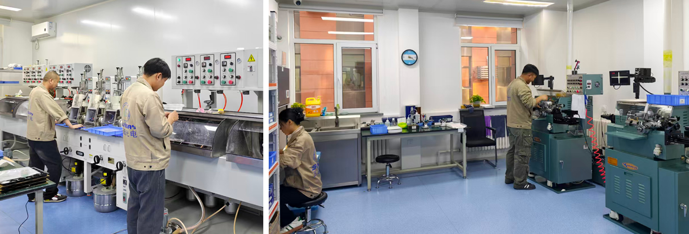
Endoscope designers face a basic conflict: the distal tip must be small enough to pass through a working channel, but it still needs to illuminate tissue and collect enough optical information for a useful image. A conventional multi-element objective may require several millimeters of axial space. A micro ball lens can perform focusing or beam expansion in a shorter package because its curved surface provides optical power in two directions.
In fiber-optic instruments, the problem is often different. A laser diode may emit from an active area only a few micrometers wide, while the fiber core may be 50 µm, 62.5 µm, or even smaller in single-mode systems. A micro spherical lens placed between them can reduce coupling loss by focusing the diode output into the fiber core. The same principle is used in fiber probes, fluorescence catheters, OCT probes, laser delivery systems, and miniature spectrometers.
The lens diameter is only one specification. A 1 mm ball lens with a refractive index of approximately 1.80 will behave differently from a 1 mm fused-silica ball lens with a refractive index near 1.45. The effective focal length, back focal length, reflection loss, and spherical aberration all change with material and wavelength.
For a first-order estimate, engineers may use the ball-lens effective focal length:
EFL ≈ nD / [4(n − 1)]
where n is the refractive index and D is the ball diameter. This equation is useful for initial layout work, but it does not replace ray tracing because a spherical ball lens can exhibit significant spherical aberration, especially at high numerical aperture.
In a miniature endoscope, one or more ball lenses can sit in front of an emitting fiber or LED. The lens increases the portion of the emitted light that reaches the target tissue. This is important when the available electrical power is limited and the distal tip cannot accommodate a large reflector.
For example, a 200 µm or 400 µm core fiber may deliver light into a ball lens with a short working distance. By changing the lens diameter, refractive index, and spacing from the fiber end face, the designer can produce either a focused spot or a wider illumination cone. A wide cone is preferred for general white-light imaging; a focused spot is more useful for fluorescence excitation or point-sensing.
Some endoscopes use coherent fiber bundles. Each individual fiber acts as one image channel, so the distal optical assembly must collect light efficiently without creating excessive cross-talk. A micro spherical lens positioned near the bundle can increase the acceptance angle and help map the scene onto the fiber face.
The relevant parameter is numerical aperture:
NA = n sin θ
where θ is the half-angle of the accepted cone and n is the refractive index of the surrounding medium. If the lens produces a cone larger than the fiber’s NA, some light will be rejected. If it produces a cone much smaller than the fiber’s NA, the available aperture is not being fully used.
Optical coherence tomography and confocal endoscopy require controlled focusing rather than simply maximum brightness. A ball lens can be combined with a fiber, spacer, and scanning mechanism to create a compact probe. In OCT, the optical design must preserve sufficient lateral resolution and depth of focus while limiting dispersion between wavelength components.
A design targeting 10 µm lateral resolution cannot be evaluated only by visual brightness. The engineer must measure spot size, axial response, signal-to-noise ratio, and focus stability across the operating wavelength. For a broadband OCT source, chromatic aberration may shift the focal plane across the spectrum, reducing resolution unless the lens material and geometry are selected carefully.
A laser diode typically emits a divergent beam with different divergence angles along its fast and slow axes. A spherical lens can collect part of that beam and focus it into a fiber. This is a compact solution, but it is sensitive to lateral, axial, and angular errors.
For a single-mode fiber, a lateral displacement of only a few micrometers can cause a measurable reduction in coupling efficiency. For a multimode fiber with a 50 µm core, the tolerance is less severe, but the source beam still needs to fit within the fiber NA. In a practical assembly, engineers often use a six-axis stage during alignment: X, Y, Z, tip, tilt, and rotation.
When light exits a fiber, it diverges according to the fiber’s mode field or numerical aperture. A ball lens placed close to the polished fiber end can create a collimated or weakly converging beam. This arrangement is used in fiber interferometers, optical switches, miniature sensors, and free-space fiber links.
The distance between the fiber end and the lens is critical. A difference of 20–50 µm can noticeably change the output beam diameter in a sub-millimeter assembly. The correct spacing should be established with optical simulation and confirmed with a beam profiler or knife-edge measurement.
In fiber sensors, the spherical lens may focus light onto a chemical coating, a reflective diaphragm, or a biological sample. The returned light is then coupled back into the same fiber or a second fiber. The lens can increase the interaction intensity at the sensing surface, but it may also reduce the measurement range if the depth of focus is too short.
Before assembling a micro spherical lens system, collect the following information and equipment.
Do not start with adhesive. First determine the fiber core diameter, fiber NA, source wavelength, desired working distance, target spot size, and available mechanical envelope. An adhesive layer that is 25 µm thicker than planned can change the lens-to-fiber spacing enough to reduce coupling.
Write down the measurable target before selecting the lens. Examples include coupling efficiency above 60%, a 1 mm illumination spot at a 5 mm working distance, or a 20° full-angle output beam.
Also define the wavelength. A lens optimized for 850 nm may not provide the same focal position at 450 nm because of material dispersion.
Choose a lens large enough to intercept the useful source beam, but small enough to fit the endoscope tip or fiber package. Compare the lens acceptance cone with the fiber NA.
If the source emits beyond the lens aperture, the unused light becomes stray light or heat. If the focused cone exceeds the fiber NA, the fiber will reject part of the beam even when the spot appears centered.
Strip the fiber carefully, cleave or polish the end face, and inspect it under magnification. Dust particles near the focal region can scatter light and create unstable power readings.
Clean the end face with a lint-free swab and approved solvent. Do not touch the fiber end with bare tools after cleaning.
Place the spherical lens in a temporary holder or vacuum pickup. Move the lens in X, Y, and Z while monitoring optical power at the fiber output.
Record the maximum power before applying adhesive. This value is the reference for later process control. A practical production limit may be to accept only assemblies retaining at least 95% of the dry-alignment power after curing.
Move the lens along the optical axis in small increments. For a miniature lens, a 10 µm step size is often more informative than a 100 µm step. Plot output power against position rather than relying on a single visual maximum.
A broad power peak indicates greater tolerance. A narrow peak may provide higher peak coupling but can create production problems when the assembly tolerance is larger than the optical tolerance.
Use the smallest adhesive volume that provides mechanical retention. Keep the adhesive away from the lens clear aperture and fiber end face. If UV adhesive is used, verify that the lens material and surrounding housing transmit enough curing radiation.
Cure in stages if the adhesive manufacturer permits it. A short tack cure followed by a full cure can reduce lens movement during assembly.
Measure coupling efficiency, output beam angle, focal position, and insertion loss after curing. Compare results at the minimum and maximum operating temperatures if the product will be used in a medical or industrial environment.
For an endoscope, also inspect the image for vignetting, field curvature, glare, and nonuniform illumination. Optical power alone cannot reveal image-quality defects.
An anonymized biomedical optics integration case involved a fiber-based fluorescence probe whose distal tip had less than 2 mm of usable diameter. The original design used a short aspheric element, but the available working distance and lens holder created an assembly longer than the catheter tip allowed. The engineering team replaced the front element with a custom glass ball lens and retained the same excitation fiber.
During the first trial, the probe produced adequate excitation power but showed a 30–40% signal variation between assemblies. The cause was not the lens material; it was axial spacing variation introduced by the adhesive meniscus. The team changed the fixture, measured the lens position under a microscope, and controlled the adhesive volume. In the next build, the output-power spread was reduced to approximately 8% across the sampled assemblies.
The case illustrates a common user problem: a micro spherical lens can fit the mechanical envelope, yet the system can still fail if the lens-to-fiber gap, tilt, or adhesive thickness is uncontrolled. The final solution was not simply “use a smaller lens.” It required a matched lens specification, a repeatable holder, six-axis alignment, and post-cure optical testing.
Problem: Two lenses with the same diameter may have different refractive indices, focal lengths, and aberration levels.
Solution: Request refractive-index data at the actual wavelength and compare effective focal length, back focal length, and ray-traced spot size.
Problem: A bright focal spot is produced, but the fiber accepts only part of the angular distribution.
Solution: Match the focused cone to the fiber NA and verify coupling with a calibrated power meter.
Problem: The adhesive shifts the lens, contaminates the clear aperture, or changes the optical spacing during cure.
Solution: Control adhesive volume, place it outside the optical path, and measure optical performance before and after curing.
Problem: The system performs well at 850 nm but loses focus or transmission at visible wavelengths.
Solution: Test at every operating wavelength. For broadband systems, quantify chromatic focal shift and select a low-dispersion material or compensating optical design.
Problem: The lens is within diameter tolerance, but the focused spot remains larger than predicted by the paraxial calculation.
Solution: Use nonparaxial ray tracing. At high NA, spherical aberration is a design characteristic of the ball geometry and may require a different diameter, index, aperture, or hybrid lens arrangement.
Problem: Dust causes scattered light, image artifacts, or unstable fluorescence readings.
Solution: Assemble in a controlled environment, inspect every optical surface, and cap or package the probe immediately after cleaning.
When contacting Sunday Optics, provide more than a requested diameter. Include the operating wavelength, material preference, fiber type, core diameter, numerical aperture, working distance, environmental range, coating requirement, and expected quantity.
A useful supplier comparison should include:
For prototypes, it is often better to purchase several diameter and index options than to commit immediately to one geometry. A small optical test matrix can reveal whether coupling loss is dominated by lens design, fiber alignment, or mechanical tolerance.
Micro spherical lenses are used in endoscopy to focus illumination, collect images, shorten distal optical assemblies, and support fluorescence or OCT probes. In fiber optics, they couple laser diodes to fibers, collimate fiber output, focus light onto sensing surfaces, and package optical functions into spaces where conventional objectives do not fit.
For reliable results, begin with numerical aperture, wavelength, working distance, and core diameter. Then select the lens material and diameter, model spherical and chromatic aberration, perform six-axis alignment, control adhesive thickness, and verify optical performance after curing. A capable optical spherical lens manufacturer such as Sunday Optics should be able to provide dimensional tolerances, material data, surface quality, coating information, and application support. The most useful design vocabulary remains micro spherical lenses for endoscopy, ball lens fiber coupling, endoscopic imaging, fiber-optic coupling, miniature optical assembly, numerical aperture, working distance, and chromatic aberration.
It is a small spherical optical element, commonly made from glass, fused silica, sapphire, or polymer, with diameters ranging from a few hundred micrometers to several millimeters. Its curved surface can focus, collimate, or collect light.
Yes, but single-mode coupling is highly sensitive to alignment. The lens must match the fiber mode field diameter and NA, and lateral displacement may need to be controlled at the micrometer level. Active alignment is normally preferred.
There is no universal best material. Fused silica offers high transmission and low thermal expansion over a broad wavelength range. High-index glass can provide stronger optical power in a smaller geometry. The correct choice depends on wavelength, numerical aperture, temperature, cost, and biocompatibility requirements.
Sometimes. A spherical lens is attractive when low cost, compact size, or easy handling is important. An aspheric lens usually provides better aberration control at higher aperture ratios, but it may require more complex manufacturing and alignment.
Measure optical power before the coupling interface and at the fiber output with calibrated detectors. Calculate coupling efficiency as output power divided by input power, after accounting for connector and transmission losses. Repeat the measurement after adhesive curing and temperature cycling.
Send the lens diameter, tolerance, material, wavelength, coating, focal requirement, fiber type, core diameter, NA, working distance, package size, quantity, and inspection requirements. A beam diagram or mechanical drawing will usually shorten the design discussion.
Hot Products


